Family Owned & Operated Since 1971• Bakersfield, CA
SKU: FLUKE-190-204-III
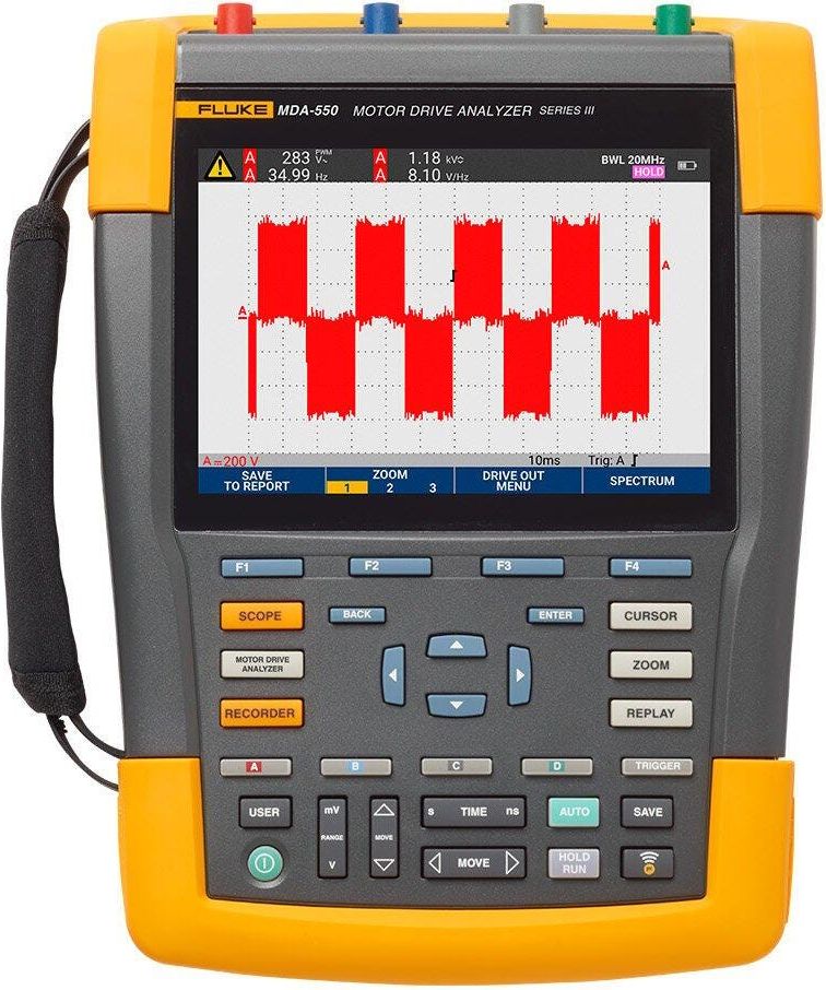
Fluke 190-204-III ScopeMeter — 4-channel, 200 MHz handheld oscilloscope with fully isolated inputs rated CAT IV 600 V / CAT III 1000 V. Connect-and-View auto-triggering, deep memory, and 200 ps timebase resolution make it ideal for troubleshooting industrial power electronics, motor drives, and control systems in the field. Rugged sealed enclosure for plant-floor, substation, and mobile use.
List price. Volume pricing available.
Get the Fluke 190 Series handheld portable oscilloscope. Install, commission, and maintain industrial machinery, automation and process controls, and power conversion electronics.
The Fluke 190-204-III ScopeMeter 4 Channel 200 MHz Color # FLUKE-190-204-III is manufactured by Fluke. Valley Instrument Service is an authorized Fluke dealer offering full sales support, NIST-traceable calibration, and expert technical assistance.
Our team can help with product selection, specs, pricing, and application support.
Contact Us or Call (661) 327-8681| Number of channels | 2 |
| Bandwidth | 60 MHz |
| Rise time | 5.8 ns |
| Number of scope inputs | 2 input channels plus external trigger |
| Channel architecture | All inputs fully insulated from each other and from ground. Inputs may be activated in any combination. |
| Input coupling | AC or DC, with ground level indicator |
| Input sensitivity | With 10:1 probe, 20 mV to 1000 V/divWith 100:1 probe, 200 mV to 10 kV/divDirect (1:1), 2 mV to 100 V/div |
| Bandwidth limiter | 20 MHz and 10 kHz |
| Polarity | Normal, Inverted, Variable |
| Input voltage | CAT III 1000 V/CAT IV 600 V rated, see General specifications for further details |
| Vertical resolution | 8 bit |
| Input impedance | 1 MΩ (± 1 %) // 15 pF (± 2.25 pF) |
| 625 MS/s(each channel) | 1.25 GS/s (each channel) |
| Record length | Up to 10,000 samples per channel |
| 10 ns/divto 4 s/div | 5 ns/divto 4 s/div |
| Time base range | Time base in a 1-2-4-sequenceSlower time/division settings using ScopeRecord Roll mode (see ‘Recorder mode’) |
| Timing accuracy | ± (0.01 % of reading + 1 pixel) |
| Glitch capture | 8 ns (10 µs/div to 2 min/div) |
| Display | 133 mm x 90 mm (5.3 in x 3.5 in) full-color high brightness LCD |
| Display modes | Any combination of channels; average on/off; replay. |
| Visible screen width | 12 divisions horizontally in scope mode |
| Digital persistence modes | Off, short, medium, long, infinite and envelope mode |
| Waveform mathematics | One (190-xx2) or two (190-x04) mathematical operations on 2 input channels (A and B, C and D): add, subtract, multiply; X-Y-mode; Frequency Spectrum using FFT |
| Acquisition modes | Normal, Averaged, Auto, Single Shot, ScopeRecord roll, glitch capture, waveform compare with automatic “Pass/Fail testing”; Replay |
| Source | Input A, B or External (via meter input) |
| Modes | Automatic, Edge, Pulse Width, N-Cycle, External (190-xx2) |
| Connect-and- View | Advanced automatic triggering that recognizes signal patterns, automatically sets up and continuously adjusts triggering, time base and amplitude. Automatically displays stable waveforms of complex and dynamic signals like motor drive and control signals. Can be switched off if preferred. |
| Pulse width triggering (on channel A) | Pulse width qualified by timeAllows for triggeringt, =t, ≠ t, where t is selectable in minimum steps of 0.01 div or 50 ns |
| Time delay | 1 full screen of pre-trigger view or up to 100 screens (=1,200 divisions) of post-trigger delay |
| Dual slope triggering | Triggers on both rising and falling edges alike |
| N-cycle triggering | Triggers on N-th occurrence of a trigger event; N to be set in the range 2 to 99 |
| Replay | Manual or continuous replay. Displays the captured 100 screens as a “live” animation, or under manual control. Each screen has date and time-stamp. |
| Replay storage | Ten sets of 100 screens each can be saved internally for later recall and analysis. Direct storage of additional sets on external flash memory drive through USB host port. |
| FFT—frequency spectrum analysis | Shows frequency content of oscilloscope waveform using Fast Fourier Transform |
| Window | Automatic, Hamming, Hanning or None |
| Automatic window | Digitally re-samples acquired waveform to get optimum frequency resolution in FFT resultant. |
| Vertical scale | Linear/Logarithmic (in volts or amps) |
| Frequency axis | Frequency range automatically set as a function of timebase range of oscilloscope |
| Waveform compare | Provides storage and display of a reference waveform for visual comparison with newly acquired waveforms. Reference is derived from an acquired waveform and can be modified in the oscilloscope. |
| Pass/Fail testing | In waveform compare mode, the oscilloscope can be set up to store only matching (“Pass”) or only non-matching (“Fail”) acquired waveforms in the replay memory bank for further analysis. |
| Advanced power and motor drive functions | V/Hz ratio, Power Factor (PF), Watts, VA, VA reactive, V-PWM (ac) and V-PWM (ac+dc) for measure- ment on pulsewidth modulated motordrives and frequency inverters |
| Dual horizontal lines | Voltage at cursor 1 and at cursor 2, voltage between cursors |
| Dual vertical lines | Time between cursors, 1/T between cursors (in Hz), voltage between markers, risetime with markers, falltime with markers; Vrms between cursors, Watts between cursors. |
| Single vertical line | Min-Max and Average voltage at cursor position; frequency and rms-value of individual frequency component in the FFT Resultant |
| Advanced functions | mA*s (current-over-time, between cursors); V*s (voltage-over-time, between cursors); W*s (energy, between cursors) |
| ZOOM | Ranges from full record overview to zoom in up to sample level, at any record length. |
| Meter inputs | Via 4 mm banana inputs, fully isolated from scope inputs and scope ground |
| Number of readings | One at a time via DMM input |
| Maximum resolution | 5,000 counts |
| Advanced meter functions | Auto/manual ranging, relative measurements (Zero reference), TrendPlot recording |
| V dc accuracy | ± (0.5 % + 6 counts) |
| 15 Hz to 60 Hz | ± (1 % + 10 counts) |
| 60 Hz to 1 kHz | ± (2.5 % + 15 counts) |
| 60 Hz to 20 kHz | — |
| Voltmeter ranges | 500 mV, 5 V, 50 V, 500 V, 1,100 V |
| Ranges | 500 Ω, 5 kΩ, 50 kΩ, 500 kΩ, 5 MΩ, 30 MΩ |
| Accuracy | ± (0.6 % + 6 counts) |
| Continuity | Beeper on < 50 Ω (± 30 Ω) |
| Diode test | Up to 2.8 V |
| Current (A) | A dc, A ac, A ac+dc using an optional current clamp or shunt Scaling factors: 0.1 mV/A, 1 mV/A to 100 V/A and 400 mV/A |
| Temperature | With optional accessories. Scale factors 1mV/°C or 1mV/°F |
| ScopeRecord Roll Mode | Dual or multiple input waveform storage mode, using deep memory |
| Input A, Input B, DualAll channels sampled simultaneously | Any combination of inputs, up to 4 channels.All channels sampled simultaneously |
| Memory depth | 30,000 data points per channel, each holding min/max pair of information |
| Min/max values | Min/max values are created at samples that are measured at high sample rate ensuring capture and display of glitches. |
| Recording modes | Single sweep, continuous roll; Start-on-Trigger (through external); Stop-on-Trigger (through external) |
| Stop-on-trigger | ScopeRecord mode can be stopped by an individual trigger event, or by an interruptionof a repetitive trigger signal, through any input channel (through External on 190-XX2 Series) |
| Horizontal scale | Time from start, time of day |
| Zoom | Ranges from full record overview to zoom in up to sample level |
| Memory | Two multiple input ScopeRecord waveforms can be saved internally for later recall and analysis. |
| Recorded timespan | 4.8 sec to 40 hr |
| Time/division in ‘view all’ mode | 0.4 s/div to 4 h/div |
| Sample rate | 125 MS/s |
| Resolution | 160 μsec ~ 4.8 sec |
| Trendplot Recording | Multiple channel electronic paperless recorder. Graphically plots, displays and stores results of up to four automatic scope measurements or a DMM-reading over time. |
| Source and display | Any combination of scope measurements, made on any of the input channels, or DMM reading (2-channel instruments) |
| Recorded time span | Up to 22 days, with a resolution of 102 seconds; up to 5.5 days for 4 readings. |
| Recording mode | Continuous recording, starting at 5 s/div with automatic time-scale compression |
| Measurement speed | Three automatic measurements per second or more |
| General specifications | Input voltage range |
| Rated maximum floating voltage | CAT III 1000 V / CAT IV 600 V (maximum voltage between any contact and earth-ground voltage level) |
| Probe input voltage VPS410-II | CAT III 1000 V / CAT IV 600 V (Maximum voltage between standard 10:1 probe tip and reference lead) |
| Probe input voltage VPS421 | CAT III 1000V / CAT IV 600V (Maximum voltage between probe tip or reference lead to GND, 2000V max between probe tip and reference lead) |
| Maximum BNC input voltage | CAT IV 300 V (maximum voltage on BNC input directly) |
| Maximum volt- age on meter input | CAT III 1000 V / CAT IV 600 V(safety designed banana input connectors) |
| Memory loca- tions (internal) | 30 waveform memories plus 10 recording memories plus 9 screen copy memories |
| 30 waveform memories | Each memory can contain up to 2 or 4 waveforms plus corresponding setups. |
| 10 recording memories | Each may contain: a 100 Screen Replay sequence, or a ScopeRecord Roll-mode recording (2 or 4 traces), or a TrendPlot recording of up to 4 measurements |
| External data storage | On PC, using FlukeView-2 Software, or direct storage on external flash memory drive (maximum 32 GB) through USB host port |
| Screencopies | On PC, using FlukeView-2 Software, or internally (in instrument) which can be copied on to external flash memory drive as .BMP-file, through USB host port |
| Volatility | Saving is done in non-volatile Flash-ROM and all data is secured, independent of battery or power status. |
| Real-time clock | Provides date and time stamp information for ScopeRecord, for 100 Screen Replay sequences and for TrendPlot recordings. |
| Design | Rugged, shock-proof with integrated protective holster. Handstrap and hangstrap included as standard.Kensington lock supported to lock down instrument when left unattended. |
| Drip and dust proof | IP 51 according to IEC60529 |
| Shock and vibration | Shock 30 g, vibration (sinusoidal) 3 g / 0.03 g2/Hz (Random), according to MIL-PRF-28800F Class 2 |
| Display size | 133 mm x 90 mm (5.3 in x 3.5 in) LCD |
| Brightness | User-adjustable, up to 300 cd/m2 |
| Size | 265 mm x 192 mm x 70 mm (10.5 in x 7.6 in x 2.8 in) |
| Weight (including battery) | 2.1 kg (4.6 lb) |
| Line power | Universal mains adapter/battery charger BC190/830 included, with detachable 2-wire power cords 100 Vac to 240 Vac, ±10 %, 50-60 Hz |
| Battery power | Re-chargeable Li-Ion battery (included). Battery swappable through easily accessible battery door at the rear of the instrument |
| Battery type (incl.) and capacity [+opt. battery] | BP290: 10.8V, 2500 mAh[BP291 (5000 mAh) optional] |
| Battery charge indicator | Battery has built-in status indicator for use with external charger, next to battery status indicator on instrument screen. |
| Battery operat- ing time (with backlight low) | Up to 3.5 using BP290 (included), up to 7 hours using BP291 (optional) |
| Battery charging time | 2½ hours using BP290; 5 hours using BP291 |
| Battery power saving functions | Auto ‘power down’ with adjustable power down time. Automatic ‘display off’ with adjustable power down time.On-screen battery power indicator |
| Operating temperature | Battery discharging: 0 °C to 40 °C (32 °F to 104 °F)Battery charging: 0 °C to 40 °C (32 °F to 104 °F) |
| Storage temperature | -20 °C to 60 °C (-4 °F to 140 °F) |
| Humidity | 0 °C to 10 °C (32 °F to 50 °F): noncondensing10 °C to 30 °C (50 °F to 86 °F): 95 % (±5 %)30 °C to 40 °C (86 °F to 104 °F): 75 % (±5 %)40 °C to 50 °C (104 °F to 122 °F): 45 % (±5 %) |
| Maximum operating altitude | CAT IV 600 V, CAT III 1000 V: up to 2000 m (6 600 feet)CAT IV 300 V, CAT III 600 V, CAT II 1000 V: up to 4000 m (13 000 feet) |
| Maximum storage altitude | 12 km (40,000 ft) |
| Interfaces | Two USB-ports provided. Ports are fully insulated from instrument’s floating measurement circuitry.USB-host port directly connects to external flash memory drive (up to 32 GB) for storage of waveform data, measurement results, instrument settings and screen copies. Alternatively, this USB-A port may be used to connect a WiFi Adapter for wireless PC connectivity. A mini-USB-B is provided which allows for interconnection to PC for remote control and data transfer under PC-control using FlukeView-2. |
| Probe calibration output | Dedicated probe-cal output with reference contact provided, fully insulated from any measurement input channel.Generator Output: 1.225 Vpp / 500 Hz square wave |
| Warranty | 3 years on main instrument, 1 year on battery and accessories |
| Battery charger/ mains adapter | BC190/830 |
| Li-Ion battery pack | BP290 (10.8V, 2500 mAh) |
| Voltage probe sets. Each set includes ground lead, hook clip; ground spring and probe tip insulation sleeve with VPS410-II-x. | 2 pcs VPS421-x, ruggedized industrial-grade probes, 100:1, 150MHz with shrouded 4mm banana tip and large jaw alligator clips (one red, one blue) |
| Test leads | TL175 (one red, one black) with test pins |
| Other | Li-Ion battery (BP290 or BP291, see above), Battery charger (BC190) with universal power cord set, Hangstrap, Handstrap (user selectable for left- or right hand use), download information for user manual and FlukeView-2 demo package (with restricted functionality), and USB interface cable for PC connectivity. Feedthrough cable terminator, 50 Ω (one per channel, 190-50x only). |
| Optional configuration | Each model is available as a ‘boxed’ version, described above, or with the optional SCC293 set included. SCC293 comprises: CXT293 rugged protective carrying case, full-version FlukeView PC software (activation code) and a WiFi dongle for wireless PC-connectivity using FlukeView-2 software. |
| Optional accessories | SCC293, VPS101 - 1:1 voltage probe; VPS510-x - wide bandwidth compact probes; i400s–current clamp; HH290–hanging hook; CXT293–protective carrying case; TRM50–BNC Feedthrough cable terminator, 50 Ω, safety designed; EBC290–battery charging bay |
This product is part of a family with 3 models. Select a model below to view details.
| Model | Price | |
|---|---|---|
FLUKE-190-204-IIICurrent | Request Quote | Viewing |
190-204-III CAL | Request Quote | View Details → |
FLUKE-190-204-III-S | Request Quote | View Details → |
Fluke 123B Industrial ScopeMeter — rugged dual-channel 20 MHz handheld oscilloscope and multimeter in one tool. Connect-and-View triggering automatically locks to any input signal; the full-colour display shows both channels simultaneously plus DMM readings. Built for CAT IV 600 V / CAT III 1000 V industrial environments. Universal international power adapter configuration.
Fluke 124B Industrial ScopeMeter — dual-channel 40 MHz handheld oscilloscope and multimeter. Connect-and-View triggering, waveform capture, built-in input isolation, and a rugged design for CAT IV 600 V / CAT III 1000 V industrial environments. Universal international power adapter configuration.
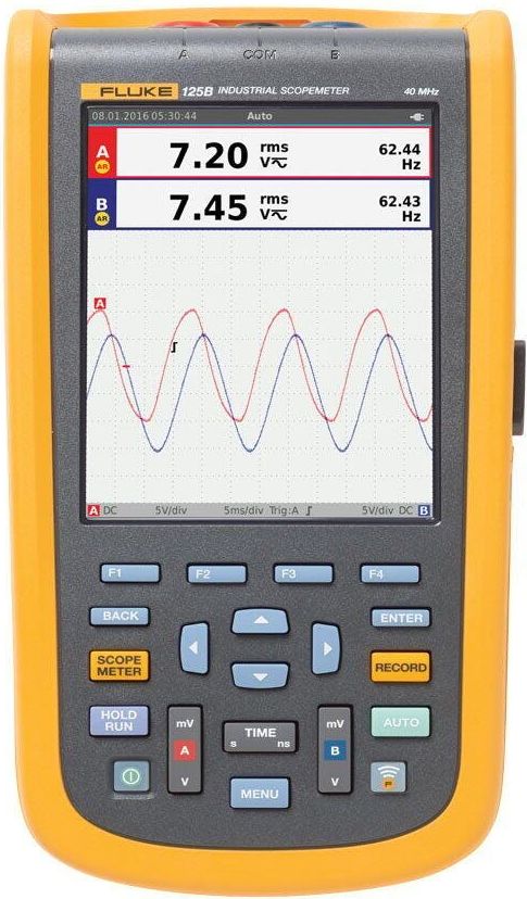
Fluke 125B Industrial ScopeMeter — dual-channel 40 MHz handheld oscilloscope with IntelliSet setup, FFT spectrum analysis, and advanced power quality measurements (VFD output, harmonics, inrush capture). Rugged CAT IV 600 V / CAT III 1000 V industrial build; two-year recording for intermittent fault capture. Universal international power adapter configuration.
Fluke 190-002-III ScopeMeter — 2-channel, 60 MHz handheld oscilloscope with fully isolated inputs rated CAT IV 600 V / CAT III 1000 V. Connect-and-View auto-triggering, deep memory, and 200 ps timebase resolution make it ideal for troubleshooting industrial power electronics, motor drives, and control systems in the field. Rugged sealed enclosure for plant-floor, substation, and mobile use.