Family Owned & Operated Since 1971• Bakersfield, CA
SKU: FLUKE-125B/INT/S
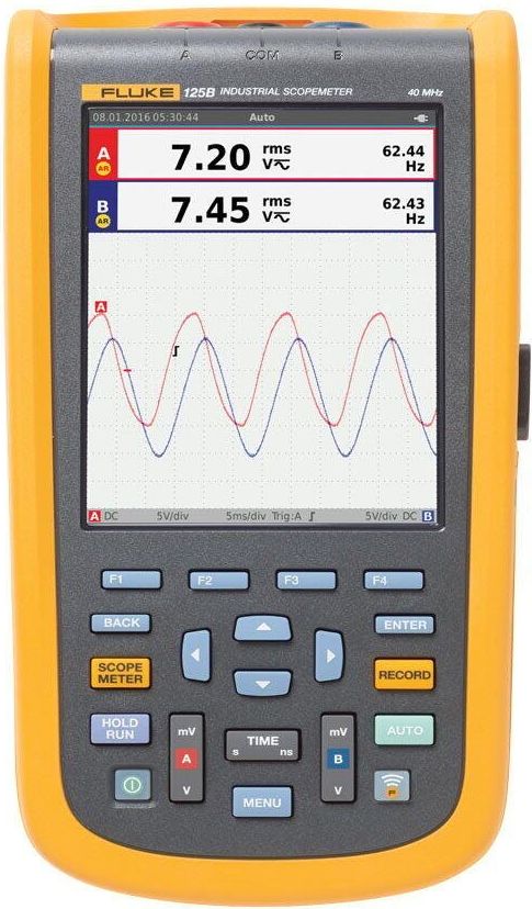
Fluke 125B Industrial ScopeMeter — dual-channel 40 MHz handheld oscilloscope with IntelliSet setup, FFT spectrum analysis, and advanced power quality measurements (VFD output, harmonics, inrush capture). Rugged CAT IV 600 V / CAT III 1000 V industrial build; two-year recording for intermittent fault capture. Universal international power adapter configuration. Includes the SCC120B industrial accessory kit: heavy-duty carry case, BC190 charger, AC adapter set, magnetic hanger, and extra test leads.
List price. Volume pricing available.
The Fluke 125B Industrial ScopeMeter is a rugged, dual-channel handheld oscilloscope built for troubleshooting on the plant floor rather than the bench. It combines a 40 MHz two-channel scope, a digital multimeter, and dedicated power-quality functions in a single sealed, portable instrument, so a technician can chase an electrical or electronic fault without carrying separate tools. IntelliSet setup automatically configures the display for the signal under test, letting you get a stable, readable trace quickly even when you don't know what you're looking at yet.
Beyond general waveform capture, the 125B is tuned for industrial power and motor-drive work. It performs FFT spectrum analysis and advanced power-quality measurements, including dedicated VFD (variable frequency drive) output measurement, harmonics analysis, and inrush-current capture for catching startup transients. A two-year recording mode logs measurements over long unattended periods to pin down intermittent faults that only appear occasionally. It is rated CAT IV 600 V / CAT III 1000 V for safe use directly in industrial electrical environments.
The Fluke 125B Industrial ScopeMeter with SCC120B Kit (International) # FLUKE-125B/INT/S is manufactured by Fluke. Valley Instrument Service is an authorized Fluke dealer offering full sales support, NIST-traceable calibration, and expert technical assistance.
Our team can help with product selection, specs, pricing, and application support.
Contact Us or Call (661) 327-8681| Input voltage | UL1/N = 120 V, UL2/N = 120 V, UL1/L2 = 208 V, 60 Hz (three-phase system) or UL1/N = 120 V, UL2/N = 120 V, UL1/L2 = 240 V, 60 Hz (single-phase system), ±10% voltage fluctuations from nominal |
| EV connector (EVC-13) | SAE J1772 socket, 16 A (type 1, 5P single-phase) |
| Internal power consumption | 2 W max. |
| Operating temperature | -4 °F to 104 °F (-20 °C to 40 °C) |
| Storage temperature | -4 °F to 122 °F (-20 °C to 50 °C) |
| Operating humidity range | 10 % to 85 % relative humidity non-condensing |
| Storage relative humidity | 0 % to 85 % non-condensing |
| Operating altitude | 6561 ft (2000 m) max. |
| Dimensions (H × W × D) | Approx. 8.66 x 4.33 x 1.77 in (220 x 110 × 45 mm) without cable assembly |
| Weight | Approx. 4.4 lb (2 kg) |
| Safety standards | IEC 61010-1, Pollution Degree 2IEC 61010-2-030 |
| Measurement category | CAT II 250 V |
| IP protection class | IP54 |
| International | IEC 61326-1: Basic Electromagnetic EnvironmentCISPR 11: Group 1, Class AGroup 1: Equipment has intentionally generated and/or uses conductively-coupled radio frequency energy that is necessary for the internal function of the equipment itself.Class A: Equipment is suitable for use in all establishments other than domestic and those directly connected to a low-voltage power supply network that supplies buildings used for domestic purposes. There may be potential difficulties in ensuring electromagnetic compatibility in other environments due to conducted and radiated disturbances.Caution: This equipment is not intended for use in residential environments and may not provide adequate protection to radio reception in such environments. |
| USA (FCC) | 47 CFR 15 subpart B. This product is considered an exempt device per clause 15.103. |
| CP States | A, B, C, D |
| CP Error “E” | On/off |
| PE Error | On/off |
| GFCI Test | Yes, test resistor of 2 kΩ connected between L1 and PE, time limitation 40 ms |
| PE Pre-Test (typical) | Visible indication >30 V on PE conductor |
| Measuring terminalsL1, L2/N, PE | Max. 250 V 50/60 Hz, CAT II 250 V |
| CP signal output terminals | Approx. ±12 V (under normal conditions), in case of wrong wiring or error of the charging station these terminals can be hazardous ≥ max. 250 V against PE |
| Outputs (for test purpose only) | Fluke 120B Series Industrial ScopeMeter® Hand-Held Oscilloscopes Specification: Oscilloscope mode |
| Without probes and test leads (with BB120) | 123B: dc to 20 MHz (-3 dB)124B and 125B: dc to 40 MHz (-3 dB) |
| With STL120-IV 1:1 shielded test leads | DC to 12.5 MHz (-3 dB) / dc to 20 MHz (-6 dB) |
| With VP41 10:1 Probe | 123B: dc to 20MHz (-3 dB)124B and 125B: dc to 40 MHz (-3 dB) |
| Without probes and test leads | <10 Hz (-3 dB) |
| Rise time, excluding probes, test leads | 123B 124B and 125B <8.75 ns |
| With BB120 | 1 MΩ//24 pF |
| Sensitivity | 5 mV to 200 V/div |
| Analog bandwidth limiter | 10 kHz |
| Display modes | A, -A, B, -B |
| Direct, with test leads, or with VP41 Probe | 600 Vrms Cat IV, 750 Vrms maximum voltage. |
| Max. floating voltage, from any terminal to ground | 600 Vrms Cat IV, 750 Vrms up to 400Hz |
| Scope modes | Normal, Single, Roll |
| Equivalent sampling | 123B: 20 ns to 500 ns/div, |
| Ranges (normal) | 124B and 125B: 10 ns to 500 ns/div |
| Real time sampling | 1 μs to 5 s/div |
| Single (real time) | 1 μs to 5 s/div |
| Roll (real time) | 1s to 60 s/div |
| Equivalent sampling (repetitive signals) | Up to 4 GS/s |
| Real time sampling 1 μs to 60 s/div | 40 MS/s |
| Screen update | Free run, on trigger |
| Source | A, B |
| @ DC to 5 MHz | 0.5 divisions or 5 mV |
| @ 40 MHz | 124B and 125B: 1.5 divisions |
| @ 60 MHz | 124B and 125B: 4 divisions |
| Slope | Positive, negative |
| Normal | Captures up to 25 ns glitches and displays analog-like persistence waveform |
| Smooth | Suppresses noise from a waveform |
| Glitch off | Does not capture glitches between samples |
| Envelope | Records and displays the minimum and maximum of waveforms over time |
| Auto set (Connect-and-View™) | Continuous fully automatic adjustments of amplitude, time base, trigger levels, trigger gap, and hold-off. Manual override by user adjustment of amplitude, time base, or trigger level. |
| Ranges | 500 mV, 5 V, 50 V, 500 V, 750 V |
| Accuracy | ±(0.5% +5 counts) |
| Common mode rejection (CMRR) | >100 dB @ dc, >60 dB @ 50, 60, or 400 Hz |
| Full scale reading | 5000 counts |
| DC to 60 Hz (V ac+dc) | ±(1% +10 counts) |
| 1 Hz to 60 Hz (V ac) | ±(1% +10 counts) |
| Accuracy for 5% to 100% of range (AC or dc coupled) | 60 Hz to 20 kHz |
| DC rejection (only VAC) | >50 dB |
| Modes | Max peak, Min peak, or pk-to-pk |
| Accuracy Max peak or Min peak | 5% of full scale |
| Accuracy Peak-to-Peak | 10% of full scale |
| Frequency range | 15 Hz (1 Hz) to 50 MHz in continuous autoset |
| Accuracy @1 Hz to 1 MHz | ±(0.5% +2 counts) |
| Max reading | 50.00 kRPM |
| Range | 2% to 98% |
| Scale factors | 0.1 mV/A, 1 mV/A, 10 mV/A, 100 mV/A, 400 mV/A, 1 V/A, 10 mV/mA |
| With current clamp | Temperature (TEMP) with optional temperature probe |
| Scale factor | 1 mV/°C and 1 mV/°F |
| 0 dBV | 1 V |
| 0 dBm (600 Ω /50 Ω) | 1 mW referenced to 600 Ω or 50 Ω |
| dB on | V dc, V ac, or Vac+dc |
| Resolution | 1 degree |
| Configurations | 1 phase / 3 phase 3 conductor balanced loads (3 phase: fundamental component only, AUTOSET mode only) |
| Power factor (PF) | Ratio between watts and VA range - 0.00 to 1.00 |
| Purpose | To measure on pulse width modulated signals, like motor drive inverter outputs |
| Principle | Readings show the effective voltage based on the average value of samples over a whole number of periods of the fundamental frequency |
| VA reactive (var) | Input A to common |
| 123B and 124B | 500 Ω , 5 kΩ, 50 kΩ, 500 kΩ, 5 MΩ, 30 MΩ |
| 125B | 50 Ω, 500 Ω , 5 kΩ, 50 kΩ, 500 kΩ, 5 MΩ, 30 MΩ |
| Measurement current | 0.5 mA to 50 nA, decreases with increasing ranges |
| Open circuit voltage | <4 V |
| Beep | <(30 Ω ±5 Ω) in 50 Ω range |
| Detection of shorts of | ≥1 ms |
| @0.5 mA | >2.8 V |
| @open circuit | <4 V |
| Polarity | + on input A, - on COM |
| Measurement voltage | Capacitance (CAP) |
| Zero Set | Set actual value to reference |
| AutoHold (on A) | Captures and freezes a stable measurement result. Beeps when stable. AutoHold works on the main meter reading, with thresholds of 1 Vpp for AC signals and 100 mV for DC signals. |
| Fixed decimal point | Activated by using attenuation keys |
| Sources | A, B |
| Single vertical line | Average, min, max and time from start of readout (in ROLL mode; instrument in HOLD) |
| Dual vertical lines | Average, min, max and time distance readout (in ROLL mode; instrument in HOLD) |
| Dual horizontal lines | High, low and peak-peak readout |
| Rise or fall time | Transition time, 0%-level and 100%-level readout (manual or auto leveling; auto leveling only possible in single channel mode) |
| Measurement Speed | Maximum 2 measurement/s |
| Record Size (min, max, average) | 2 M readings for 1 channel |
| Recorded Time Span | 2 weeks |
| Maximum number of events | 1024 |
| Maximum sample rate | 400 K sample/s |
| Size Internal memory | 400 M samples Recorded Time |
| Span internal memory | 15 minutes at 500 μs/div11 hours at 20 ms/div |
| Record Size SD card | 1.5 G samples |
| Recorded Time Span SD card | 11 hours at 500 μs/div14 days at 20 ms/div |
| Readings | Watt, VA, var, PF, DPF, Hz |
| When selected: total (% r) | ±(2% + 6 counts) |
| When selected: fundamental (% f) | ±(4% + 4 counts) |
| DPF | 0.00 to 1.00 |
| PF | 0.00 to 1.00, ±0.04 |
| Number of Harmonics | DC to 51 |
| Readings / Cursor readings (fundamental 40 Hz to 70 Hz) | Vrms / Arms /Watt |
| Watt, VA, var ranges (auto) | Includes frequency of fundamental, phase Angle and K-factor (in Amp and Watt) |
| Type | Subtype |
| AS-i | NEN-EN50295 |
| CAN | ISO-11898 |
| Interbus S | RS-422 |
| RS-232 | RS-232/EIA-232 |
| RS-485 | RS-485/EIA-485 |
| Foundation Fieldbus | H1 |
| DP | EIA-485 |
| PA | 61158 type 1 |
| Profibus | Miscellaneous |
| Vertical | 10 div of 40 pixels |
| Horizontal | 12 div of 40 pixels |
| External | Via Power Adapter BC430 |
| Power consumption | 5 W typical |
| Input connector | 5 mm jack |
| Internal | Via Battery Pack BP290 |
| Battery power | Rechargeable Li-Ion 10.8 V |
| Operating time | 7 hours with 50% backlight brightness |
| Charging time | 4 hours with test tool off, 7 hours with test tool on |
| Allowable ambient temp | 0 to 40 °C (32 to 104 °F) during charging |
| Memory | Internal memory can store 20 data sets (screen waveform and setup) |
| Size | 259 x 132 x 55 mm (10.2 x 5.2 x 2.15 in) |
| Optically isolated | Transfer screen copies (bitmaps), settings and data |
| USB to PC/laptop | OC4USB optically isolated USB adapter/cable, (optional), using FlukeView® software for Windows®. |
| Optional WiFi adapter | Fast transfer of screen copies (bitmaps), settings and data to PC/laptop, tablet, smartphone, etc. A USB port is provided for attaching the WiFi dongle. Do not use the USB port with a cable for safety reasons. |
| Interface | Environmental |
| Environmental | MIL-PRF-28800F, Class 2 |
| Battery Operation | 0 to 40 °C (32 to 104 °F) |
| Power Adapter Operation | 0 to 50 °C (32 to 122 °F) |
| Storage | -20 to 60 °C (-4 to 140 °F) |
| @ 0 to 10 °C (32 to 50 °F) | Non-condensing |
| @ 10 to 30 °C (50 to 86 °F) | 95% |
| @ 30 to 40 °C (86 to 104 °F) | 75% |
| @ 40 to 50 °C (104 to 122 °F) | 45% |
| Operating at 3 km (10,000 feet) | CAT III 600 V |
| Operating at 2 km (6,600 feet) | CAT IV 600 V |
| Korea (KCC) | Class A Equipment (Industrial Broadcasting & Communication Equipment) |
| Output power | <100 mW |
| Enclosure protection | IP51, ref: EN/IEC60529 |
| General | IEC 61010-1: Pollution Degree 2 |
| Measurement | IEC 61010-2-033: CAT IV 600 V/CAT III 750 V |
| Direct on input or with leads | 600 Vrms CAT IV for derating |
| With Banana-to-BNC Adapter BB120 | 600 Vrms for derating |
| Max. floating voltage from any terminal to ground | 600 Vrms Cat IV, 750 Vrms up to 400 Hz |
| Maximum voltage | 1000 V |
| Maximum resolution | 10 µV |
| AC bandwidth | 20 kHz with low pass filter; 3 dB @ 1 kHz |
| Maximum amps | 10 A (20 A for 30 seconds maximum) |
| Amps accuracy | ±(0.2% + 2) |
| Maximum resistance | 50 MΩ |
| Maximum capacitance | 9,999 µF |
| accuracy | ±(1% + 2) |
| Maximum frequency | 200 kHz |
| Maximum duty cycle | 99.9% |
| Temperature measurement | –200.0 °C – 1090 °C–328.0 °F – 1994.0 °Fexcluding probe |
| 80 BK temperature probe | –40.0 °C – 260 °C–40.0 °F – 500 °F, 2.2 °C or 2% whichever is greater |
| Maximum conductance | 60.00 nS |
| Duty cycle range | Accuracy |
| Diode | Environmental Specifications |
| Humidity (without condensation) | 0% – 90% (0 °C – 35 °C)0% – 70% (35 °C – 55 °C) |
| Operating Altitude | 2000 m |
| Overvoltage category | EN 61010–1 to 1000 V CAT III, 600V CAT IV |
| Agency approvals | CE, CSA, RCM |
| Digital | 6000 counts updates 4/sec.19,999 counts in high–resolution mode |
| Analog | 32 segments, updates 40/sec |
| Frequency | 19,999 counts, updates 3/sec at > 10 Hz |
| Warranty | Lifetime |
| Battery Life | Alkaline |
| Shock | 1 Meter drop per IEC 61010–1:2001 |
| Vibration | Per MIL–PRF–28800 for a Class 2 instrument |
This product is part of a family with 4 models. Select a model below to view details.
| Model | Price | |
|---|---|---|
FLUKE-125B/NA | Request Quote | View Details → |
FLUKE-125B/INT | Request Quote | View Details → |
FLUKE-125B/NA/S | Request Quote | View Details → |
FLUKE-125B/INT/SCurrent | Request Quote | Viewing |
Fluke 123B Industrial ScopeMeter — rugged dual-channel 20 MHz handheld oscilloscope and multimeter in one tool. Connect-and-View triggering automatically locks to any input signal; the full-colour display shows both channels simultaneously plus DMM readings. Built for CAT IV 600 V / CAT III 1000 V industrial environments. Universal international power adapter configuration.
Fluke 124B Industrial ScopeMeter — dual-channel 40 MHz handheld oscilloscope and multimeter. Connect-and-View triggering, waveform capture, built-in input isolation, and a rugged design for CAT IV 600 V / CAT III 1000 V industrial environments. Universal international power adapter configuration.
Fluke 190-002-III ScopeMeter — 2-channel, 60 MHz handheld oscilloscope with fully isolated inputs rated CAT IV 600 V / CAT III 1000 V. Connect-and-View auto-triggering, deep memory, and 200 ps timebase resolution make it ideal for troubleshooting industrial power electronics, motor drives, and control systems in the field. Rugged sealed enclosure for plant-floor, substation, and mobile use.
Fluke 190-102-III ScopeMeter — 2-channel, 100 MHz handheld oscilloscope with fully isolated inputs rated CAT IV 600 V / CAT III 1000 V. Connect-and-View auto-triggering, deep memory, and 200 ps timebase resolution make it ideal for troubleshooting industrial power electronics, motor drives, and control systems in the field. Rugged sealed enclosure for plant-floor, substation, and mobile use.